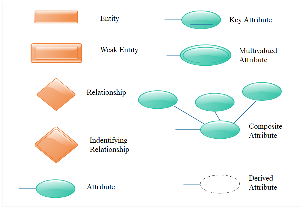
E-R diagram in DBMS(ER Notation)
- There is no standard for representing data objects in ER diagrams. Each modeling methodology uses its own notation.
- All notational styles represent entities as rectangular boxes and relationships as lines connecting boxes.
- Each style uses a special set of symbols to represent the cardinality of a connection. The notation used in this document is from Martin.
- The symbols used for the basic ER constructs are:
- Entities are represented by labeled rectangles. The label is the name of the entity. Entity names should be singular nouns.
- Relationships are represented by a solid line connecting two entities. The name of the relationship is written above the line. Relationship names should be verbs.
- Attributes, when included, are listed inside the entity rectangle. Attributes which are identifiers are underlined. Attribute names should be singular nouns.
- Cardinality of many is represented by a line ending in a crow's foot. If the crow's foot is omitted, the cardinality is one.
- Existence is represented by placing a circle or a perpendicular bar on the line. Mandatory existence is shown by the bar (looks like a 1) next to the entity for an instance is required. Optional existence is shown by placing a circle next to the entity that is optional.
How to draw E-R Diagram ?
While designing database using E-R diagrams, you should use the following guidelines:
- Do not introduce unwanted attributes.
- Merge the entities with common attributes or purposes.
- Decompose complex entities to simplify them. Do it by decomposing complex attributes into sub-attributes.
Symbol & Meaning
